![]() Optical
Fibre Handling Guidelines:
Optical
Fibre Handling Guidelines:
Please read this before using TTC optical components!!!
Contacts --
Please contact Sophie Baron for any questions about the TTC system.
![]() Optical
Fibre Handling Guidelines:
Optical
Fibre Handling Guidelines:
Please read this before using TTC optical components!!!
The TTC system was initially developed by RD12, an LHC Common Project financed by EP and SL Divisions and the four LHC experiment collaborations.
The RD12 collaboration included TTC representatives from ALICE, ATLAS, CMS and LHCb as well as CERN EP/ATE, EP/CMD, EP/CME, EP/MIC and SL/BI Groups, Rutherford Appleton Laboratory, the FERMI project and additional industrial optoelectronics and micromechanics partners Honeywell Ltd and Lemo SA.
The overall TTC system architecture provides for the distribution of synchronous timing, level-1 trigger, and broadcast and individually-addressed control signals, to electronics controllers with the appropriate phase relative to the LHC bunch structure, taking account of the different delays due to particle time-of-flight and signal propagation. Within each trigger distribution zone, the signals can be broadcast from a single laser source to several hundred destinations over a passive network composed of a hierarchy of optical tree couplers.
At the start of coast, the LHC beams will have a cosine-squared longitudinal bunch profile with a total base length of 1.12 ns (202 ps rms). RF phase fluctuations will cause the bunches to be displaced by up to ±140 ps relative to the reference clock. Bunch-to-bunch variation due to the transient beam loading in the RF cavities will result in a further fast variation of about ±14 ps.
For the colliding bunches, it is estimated that at the start of coast 95% of the distribution will be within a length of 18 cm (600 ps). During 10 hours of coast the bunch length will increase by 30% and the cosine-squared distribution will migrate to a Gaussian one (with the tails truncated by the bucket limit) having an rms value of 364 ps.
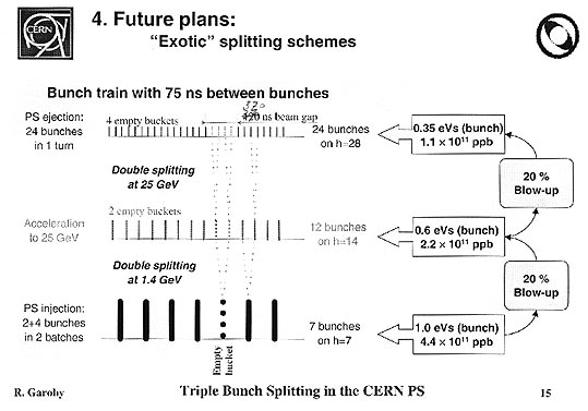
It is now planned that the first LHC magnet will be installed in January 2004 and injection in two octants will be tried in early 2006. Installation should be complete and cool down started in October 2006. Commissioning with the first beams should take place in April 2007 and physics should start in mid-2007. It is possible that initial running will be with a bunch spacing of 75 ns and a peak luminosity of 1.3x10^33.
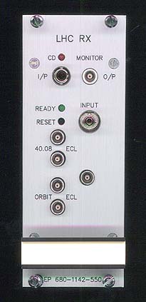
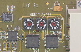
The 40.08 MHz LHC bunch-crossing clock and 11.246 kHz orbit signals are broadcast over the same singlemode optical fibres from RD12 high-power laser transmitters which have been installed in the Prevessin Control Room (PCR). The combined signals will be received at each of the 4 underground LHC experiment areas by a TTC machine interface (TTCmi) minicrate containing an LHCrx module. The jitter of the received clock is reduced in the TTCmi to less than 10 ps rms by a narrow bandwidth PLL with a low-noise VCXO having low sub-harmonic feedthrough.
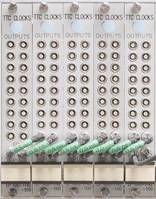
The TTCmi can be equipped with a variable number of electrical clocks fanout (TTCcf) modules which allow the low-jitter clock to be distributed by short coaxial cables to the encoders of the laser transmitters for each trigger distribution zone. The TTCmi also incorporates a master phase adjustment for the orbit signal and facilities for monitoring clock signal quality.
Two TTCmi have been constructed for each LHC experiment and they have initially been used at the GIF, X5A, X5B and X7 test beam facilities in the West Area and H2, H4, H6 and H8 in the North Area. At each LHC experiment, the second TTCmi will be installed adjacent to the main one and fed via an independent optical fibre from the PCR so that an online spare will be continuously available.
The TTCmi is described in the RD12 working document "TTC machine interface (TTCmi) User Manual" by B.G. Taylor.
A review of the system is given in "Timing Distribution at the LHC", B.G. Taylor, presented at the Eighth Workshop on Electronics for LHC Experiments, Colmar, 9-13 September 2002.
A second PCR transmitter has been installed for broadcasting the ramping SPS RF/5 for beam instrumentation development work in the SPS machine. A third PCR transmitter has been installed to allow independent timing signals to be broadcast for the beam instrumentation of the two LHC rings, which will be run with slightly different radio frequencies during beam-steering operations. A fourth transmitter has been installed as a spare and a fifth transmitter is kept in reserve.
The RD12 TTC system operates at 1310 nm, at which wavelength there is less eye danger than at 850 nm and the chromatic dispersion of normal optical fibre is negligible. The transmitter primary PLL plus encoder jitter when transmitting PRBS data is about 10 ps rms. Using a TTCrx timing receiver ASIC, the timing reference can be recovered from the received encoded signal sequence with a jitter of less than 100 ps rms relative to the LHC clock input when transmitting PRBS data. In applications (such as the ALICE TOF system) requiring the distribution of only the 40.08 MHz clock, it can be received without a TTCrx with a jitter of less than 20 ps rms.
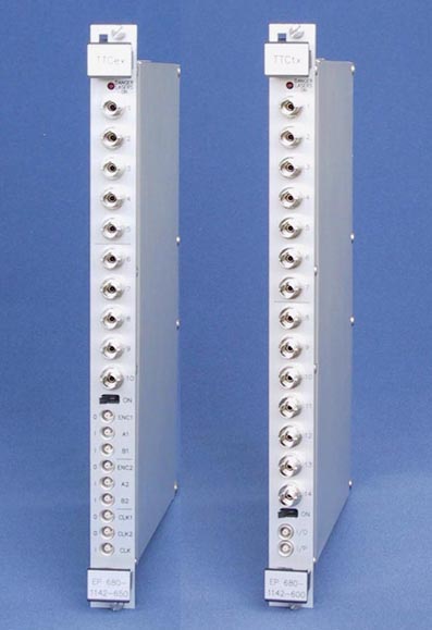
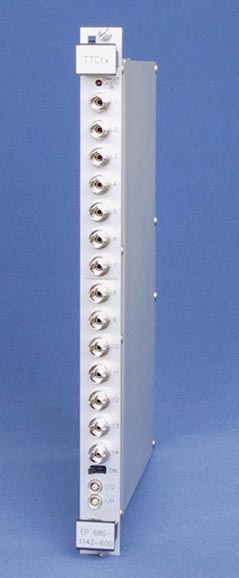
For the local distribution of the TTC signals at the experiments, compact and flexible 6U VME-size laser transmitters (TTCex and TTCtx) have been developed. These modules can be used separately or in combination to match the requirements of a wide range of TTC partition sizes. User notes for these modules are given in the RD12 working document "TTC Laser transmitter (TTCex, TTCtx, TTCmx) User Manual" by B.G. Taylor.
The TTCex encoder/transmitter module incorporates dual encoders driven by an internal VCXO/PLL with very low jitter and can deliver the optimum optical signal level (-19 dBm) through 1:32 tree couplers to 320 destinations. The TTCtx transmitter module does not include encoders and can supply 448 destinations. One TTCex or TTCtx module can serve two independent small partitions, or several modules can be linked together to serve one large partition.
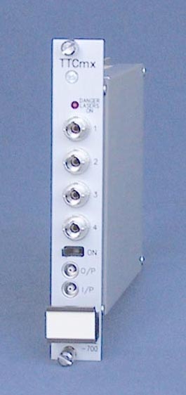
A 3U-high mini-version of the TTCtx (TTCmx) is also available for optional use in TTCmi crates, for TTC repeaters and for upgrading TTC transmitter minicrates. Each TTCmx can supply 128 destinations and the modules can be daisy-chained for larger partitions.
A low-power VME-size LED transmitter module (TTCvx) is available which can deliver the same signal level to 4 destinations for system integration prototyping work. The TTCvx is described in the draft RD12 working document "TTCvx Technical Description and Users Manual" by P. Gällnö.
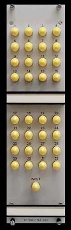
At the experiments, single mode passive optical tree couplers are used to fan out the signals from the laser transmitters to the large numbers of destinations in each trigger partition. Optical coupler components have small size, low mass and unlimited bandwidth. Suitable 1:16 and 1:32 TTC optical couplers (TTCoc) are available mounted in 1U 19" rack trays with a depth of 23cm. They require no operating power and are potentially highly reliable. The singlemode tree couplers at the PCR transmitters are mounted in plug-in modules
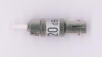
In order to allow for the overall insertion loss (splitting loss + excess loss) of TTCoc optical tree couplers, the power level at each of the outputs of TTCex, TTCtx and TTCmx transmitter modules is about 100 times that required by a single receiver. If an output is connected directly to a single receiver for test purposes, a 20 dB optical attenuator should be inserted at the transmitter output to avoid overloading. Because of modal distribution factors, not all attenuator technologies are appropriate for this application. Attenuators can be ordered to TS/EL, at the approximate price of 37 Euros.
The optical attenuators employ a spring-loaded ferrule/receptacle. To mount the attenuator, first connect the optical fibre to it and then mate the attenuator with the transmitter module. Do not try to mate the attenuator with the transmitter module without the optical fibre attached to it.
When measuring TTC system optical signal levels with a power meter be sure that the instrument calibration for 1310 nm wavelength is selected.
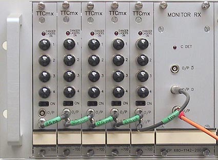
Active TTC repeaters are appropriate for a number of LHC machine applications in which the optical timing signals received from the PCR are rebroadcast to the beam instrumentation systems. The repeaters can be configured by the direct interconnection of a modular optoelectronic receiver with the required number of TTCmx laser transmitter modules. The modules can be housed in an inexpensive minicrate with 5v power only. The LHC machine will use 40 such minicrates and the first 8 are being installed in the SPS.
The 1310 nm optical signal broadcast from the PCR to the TTCmi at each experiment area is IEC 60825 Class 1 (intrinsically safe), even prior to the level-adjustment attenuator. The high power PCR transmitters themselves are in a controlled access area and before leaving this area their outputs are divided by 1:32 optical tree couplers having an insertion loss of about 19 dB.
The TTCex, TTCtx and TTCmx laser transmitters for local TTC signal distribution at the experiments (and LED transmitters such as the TTCvx) are also Class 1. However, the direct individual outputs from the laser transmitters should not be merged into a fibre ribbon equipped with an array connector since this could create a single extended source of greater hazard level. (Multifibre cable or ribbon fibres can be used as long as they are terminated by a single fibre breakout). The modules have a manual disable switch, laser emission indicator, warning label and facilities for interlock connection.
On the other hand, for the distribution fibres to the final TTCrx destinations (i.e., the outputs from the TTCoc optical tree couplers) the hazard level would remain Class 1 even if they were merged in ribbon fibres terminated with MT-12 connectors.
Notwithstanding this, it is strongly recommended never to view output optical connectors or fibre ends either with the naked eye or with any kind of optical instrument.
For optical transmission over a single fibre the TTC signals are encoded by a 160.32 MBaud biphase mark encoder which time-division multiplexes 2 channels using a balanced DC-free code.
The low-latency A-channel is dedicated to the transmission of level-1 trigger accepts. The B-channel transmits framed and formatted broadcast and individually-addressed commands and data using forward error-correction for high reliability. The format supports up to 16K receivers per distribution zone, each of which may be associated with up to 256 internal and external subaddresses.
An indication of the latency of the TTC distribution system for broadcasting the level-1 trigger accept (L1A) can be obtained by summing the component delays as follows. Note that these are preliminary measurements made with sample system components and should not be taken as representing absolute worst case conditions.
The delay from the L1A input socket of a TTCex laser encoder/transmitter module to the L1A output pin of the TTCrx timing receiver ASIC at a destination (when using the HFBR-2316T photodiode+preamp) is 68 ns plus the propagation delay of the external optical fibre network. The corresponding delay for a TTCtx transmitter driven via a 1 ns coax cable by the encoder output of a TTCex is 73 ns. For a TTCmx transmitter driven via a 1 ns coax cable by an encoder module in a TTCmi or minicrate the delay is 61 ns. The delay with the TRR-1B43 photodiode+preamp has not yet been measured and may be expected to be somewhat greater. The measurements were made with the DMILL 100 BGA version of the TTCrx, not the latest 144 fpBGA version.
These are the delays with the TTCrx internal programmable deskews set to minimum. Note that to permit the full range of adjustment the fine and coarse deskews may initially be set to their mid values of 12.5 ns and 200 ns respectively.
The propagation delay of the optical fibre at 1310 nm is 4.9 ns per metre. Special direct fibre cable routes are foreseen between the TTC equipment in the underground service caverns and the detectors. Fibre delays within the transmitter modules are included in the above figures. The delay in the external single mode 1:32 TTCoc optical tree couplers is 30 ns.
When transmitter modules are daisy-chained to drive large partitions, note that the delay between the input and output sockets of a TTCtx is 2 ns and 0.5 ns coax cables are required to link TTCtx modules in adjacent slots. The delay between the input and output sockets of a TTCmx transmitter is 1.5 ns.
The internal delay added by routing the L1A signal through a TTCvi module (using the L1A IN 0 input) is 3 ns. A 1 ns coax cable is sufficient to interconnect a TTCex with a TTCvi up to 4 slots to the left or right of it in the same VME crate. The delay of the coax cable from the L1A output of the central trigger processor to the TTCvi input must be added, as well as that of the L1A fanout for the different trigger partitions if this is not integrated within the CTP itself.
The delays of all components following the L1A output of the TTCrx must of course be added to the latency of the RD12 part of the TTC system to obtain the total.
The TTC transmitter encoders can be driven by a TTC-VMEbus interface module (TTCvi) which allows programmable selection of trigger source and synchronous signal timing relative to the LHC machine orbit. The TTCvi can be accessed by multiple VMEbus masters including interfaces to the detector control system or a local workstation. It includes a programmable trigger emulator and pseudo-orbit generator for test purposes.
The TTCvi is described in the RD12 working document "TTC-VMEbus Interface (TTCvi)" by Ph. Farthouat and P. Gällnö. A shorter overview is given in the paper "Modules Development for the TTC System", P. Gällnö, presented at the Fifth Workshop on Electronics for LHC Experiments, Snowmass, Colorado, 20-24 September 1999.
Following feedback from users a MkII version of the TTCvi has been developed which incorporates a number of improvements and modifications and a special feature required for the LHC beam instrumentation application. This MkII version, which is almost fully software compatible with the first version, is now available from the Electronics Pool. LHCb will incorporate the required TTCvi functionality in their readout supervisor module.
The RD12 system uses singlemode fibre for the distribution of the machine timing signals from the PCR to the LHC experiment areas. These fibres are installed by the EL Group of ST Division. The approximate fibre lengths from the PCR to the surface buildings are as follows:
The LHC timing generators will finally be located in a new Faraday cage at SR4, in the vicinity of the RF system of the machine. 9.5 km of single mode optical fibres will be used to transmit the timing signals from SR4 to the PCR.
The system uses mostly single mode fibre for the local TTC distribution at the experiments, which will require a large number of optical tree couplers. Standard 9/125 µm SMF-28 is suitable for these installations and for safety reasons sheathing should be LSZH (low smoke zero halogen). The connectors used for most installations are the industry-standard ST/PC type. These are the most popular and lowest cost single fibre connectors in use today and are available from many manufacturers.
Ready-connectorised multimode optical patchcords for interconnecting the RD12 TTC distribution modules have been standardised in CERN stores in a range of overall lengths as follows:
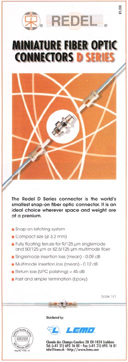
Since conventional optical single-fibre connectors and optoelectronic receivers are relatively bulky, a subminiature optical fibre connector and active device mount have been developed for special applications which allow timing receivers to be much smaller than telecommunications components. This "RD12" connector, which is now produced industrially by Lemo SA, has very low mass and is made from radiation-hard materials so that it may be appropriate for use within particle detectors. A subminiature connector-connector coupling bush has also been developed and this is being offered as an alternative to fibre splicing.
The RD12 connector has successfully undergone qualification tests specified by Boeing for airborne applications. The manufacturer should be contacted directly for further information.
Various optoelectronic receivers can be used in the TTC system.
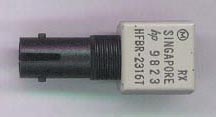
Early systems used a photodiode+preamplifier (Agilent HFBR-2316T) which is housed in an ST-connectorised synthetic package containing an InGaAs photodiode and Si bipolar transimpedance amplifier with a typical bandwidth of 125 MHz. It has a single-ended output and very limited dynamic range and is not recommended for new designs.
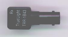
The current baseline choice is the TrueLight TRR-1B43-000 photodiode+preamplifier, which is much less expensive. This device has a CMOS preamplifier with differential outputs and AGC, which greatly extends the dynamic range. Although the 1B43 is physically similar to the 2316, note that it is not pin-compatible (in particular, the power supply polarity is reversed). Small quantities of 1B43 components can be supplied to TTC developers for evaluation purposes by B.G. Taylor and a volume procurement is being organised by the Microelectronics Group (contact A. Marchioro).
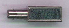
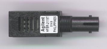
Modular optoelectronic receivers with ECL-compatible outputs, such as Tyco 269050-1 or Agilent HFBR-2119T, can be used for applications in which several TTCrx ASICs are driven on a short bus from each optoelectronic receiver. Alternatively the 1B43 can be used in conjunction with a fibre optic postamplifier such as the Philips/Signetics NE/SA5225D or TZA3034 data sheet.
To optimise the jitter and dynamic range an appropriate attenuator/equaliser must be connected between the output of the different types of photodiode+preamplifier or modular optoelectronic receiver and the input of the TTCrx ASIC. For low jitter the connections between these components must be as short as possible.
Tests have shown that the photodiodes generate SEU spurious signals when irradiated with neutrons or protons of energy higher than 20 MeV. A series of irradiation tests of the HFBR-2316T and TRR-1B43-000 have been carried out by M. Gastal and both devices have been found to meet the qualification requirements of the LHC experiments. Details are given in the draft paper "Radiation Qualification of Commercial off-the-shelf p-i-n Receivers for the TTC system", M. Gastal and P. Moreira, submitted to the 9th Workshop on Electronics for LHC Experiments, Amsterdam, 29 September - 3 October 2003.
A timing receiver ASIC (TTCrx) which delivers the TTC signals to front-end electronics controllers has been developed by the CERN Microelectronics Group. The TTCrx can deliver the full range of decoded and deskewed signals, including synchronous commands and 12-bit bunch numbers and 24-bit event numbers matched with each level-1 trigger accept. The TTCrx also incorporates a serial output for driving a reduced-functionality receiver for use in inner detector front-end electronics where low mass and power consumption are particularly critical.
Descriptions of the TTCrx are given in the papers "Receiver ASIC for Timing, Trigger and Control Distribution in LHC Experiments", J. Christiansen, A. Marchioro, P. Moreira and A. Sancho, IEEE Trans. Nuclear Science, Vol. 43, June 1996, pp. 1773-1777 and "TTCrx, an ASIC for Timing, Trigger and Control Distribution in LHC Experiments", J. Christiansen, A. Marchioro and P. Moreira, presented at the Second Workshop on Electronics for LHC Experiments, Balatonfüred, 23-27 September 1996.
Detailed technical specifications of the TTCrx are given in the periodically updated "TTCrx Reference Manual", J. Christiansen, A. Marchioro, P. Moreira and T. Toifl. For In-System Programmability, download the BSDL file (Boundary Scan Description Language).
Initially a number of prototype TTCrx ASICs were fabricated through CMP and supplied to users in a 15x15mm 100 BGA package. The TTCrx design was then improved and migrated to DMILL radiation-hard technology. 44 working 100 BGA-packaged samples of the complete rad-hard TTCrx were received from the preliminary MPW run and initial total dose tests, neutron irradiation and an SEU test were carried out with good results. However, the tests showed that the photodiodes generate SEU spurious signals when irradiated with neutrons or protons of energy higher than 20 MeV. Details are given in the paper "Measurements of Radiation Effects on the Timing, Trigger and Control Receiver (TTCrx) ASIC", T. Toifl, P.Moreira and A. Marchioro, presented at the Sixth Workshop on Electronics for LHC Experiments, Kraków, 11-15 September 2000.
In the DMILL version of the TTCrx ASIC the JTAG controller is supplemented by an I2C bus interface. This interface allows an external I2C controller to write and read all the TTCrx internal registers. An initialization PROM is no longer required for this final version, which also supports more user-defined broadcast codes and has lower trigger latency. A list of the changes which have been implemented in the DMILL TTCrx is given in "TTCrx Modifications".
A first engineering run (8 wafers, 2880 chips) of the TTCrx was launched at the end of June 2000. The run included both the existing version of the chip (Version 3.1) and also a slightly modified design (Version 3.2) which is more resistant to photodiode SEU. The chips were delivered in February 2001 and were packaged in a new fine pitch (1mm) 13x13mm 144 fpBGA package. The yield was about 75%. Preliminary irradiation tests indicate that the new Version 3.2 is a factor of 750 less sensitive to photodiode SEU than Version 3.1. A second engineering run of 10 wafers was made in 2001/02 with new masks for Version 3.2 only.
The total requirement for TTCrx ASICs is estimated to be about 22,000 and a production run of 58 wafers was launched in November 2002. The chips have now been received and a first evaluation indicates that the yield is better than 80%.
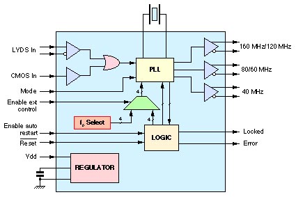
For some applications, such as clocking high-speed serializers, the jitter of the raw 40.079 MHz clock output of the TTCrx is too high. An auxiliary VCXO/PLL ASIC is now being developed by the Microelectronics Group for use as an optional auxiliary jitter filter. The QPLL will provide 3 LVDS clock outputs in 2 frequency multiplication modes from a CMOS or LVDS clock input.
An MPW submission of the QPLL chip was made in September 2002 and 186 chips have now been received at CERN. The QPLL has been tested and found to be functional, with an output clock jitter of 16 ps rms when driven by a TTCrx. A preliminary data sheet, a preliminary QPLL User Manual and an information website are available. Groups requiring QPLL chips for prototype development should contact P. Moreira.
Please note that the QPLL locking range is ~ [40.0749MHz-40.0823MHz].
Please take note of the application note of the crystal (CC1A, CC1F Family) to be used, and to the custom specification for CERN. The crystal units ordered via the CERN contract will be pre-tested by the manufacturer according to this document.
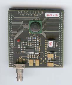
Initially the Microelectronics Group developed a small mezzanine evaluation board which supported the 100 BGA TTCrx and associated components such as the photodiode+preamp.
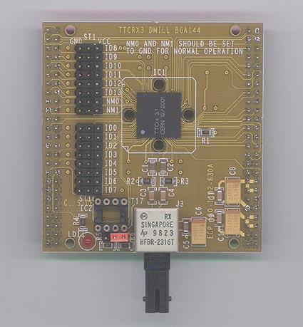
A revised TTC receiver mezzanine (TTCrm) has been designed for the 144 fpBGA ASICs. It is pin-compatible with earlier versions but the photodiode+preamp has been physically relocated. The schematic diagram of the board provides an implementation example and this mezzanine board is available from the Electronics Pool. The present version of the board requires modification to accept the TRR-1B43 photodiode+preamp.
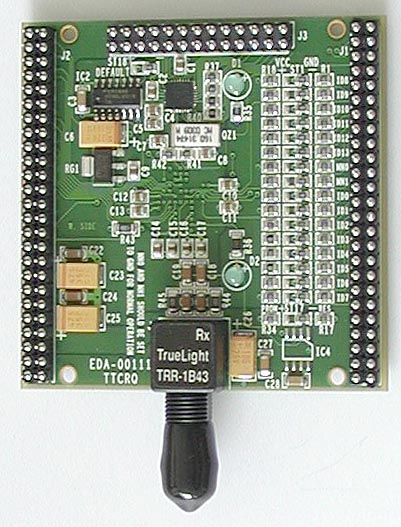
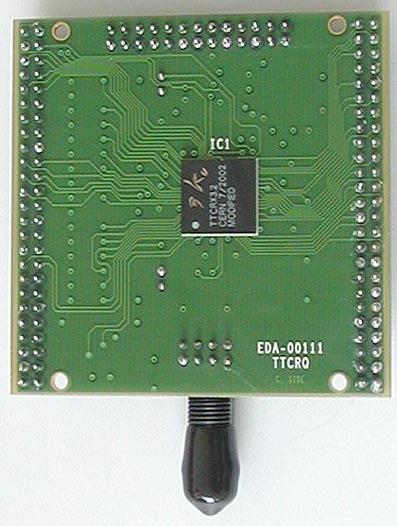
A new version of the TTCrm mezzanine board (TTCrq) has been designed by the Microelectronics Group which incorporates a QPLL and its associated components. The TTCrq has the 1B43 photodiode+preamp, relocated to the connector side of the pc board, which reduces the overall height of the mezzanine to 13.6 mm. This allows the TTCrq to be mounted in a single-width VMEbus module. The TTCrx is mounted on the external side of the board for adequate cooling.
As far as possible the new TTCrq is backward-compatible with the TTCrm. The pinout of the existing J1 and J2 connectors remains unchanged and the additional signals are provided on a new J3 connector at the rear of the card. A Preliminary description (Rev 0.1) of the TTCrq is available.
Please note that the TTCrq using the QPLL has a locking range of ~ [40.0749MHz-40.0823MHz].
For applications in which several TTCrx will be housed in the same VME crate, the University of Maryland has developed a TTCrx mezzanine board equipped with PMC connectors. These mezzanine boards, which will be used in the CMS HCAL readout, can be connected on a short differential LVPECL bus driven by a common optoelectronic receiver. Details are available from Tullio Grassi.
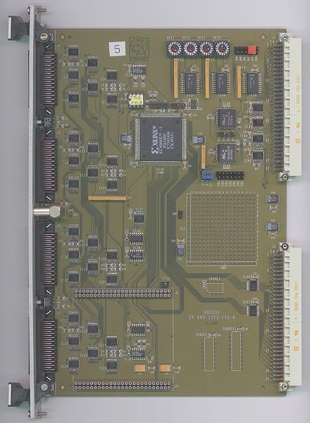
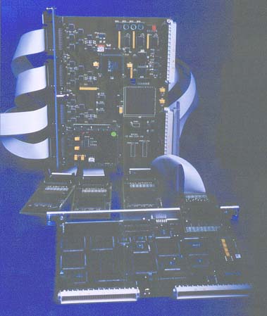
The Beam synchronous timing Receiver interface for Beam Observation system (BOBR) acts as an interface between the TTC distribution network and its receiving end users. The BOBR is designed to recover the 2 distributed clocks, decode and store all BST messages and make them available to the front-end electronics controllers. The BOBR is a VME format card, designed to interface a VME crate with up to 2 different TTC networks, and provid all timing signals required to synchronize the different beam instrumentation systems.
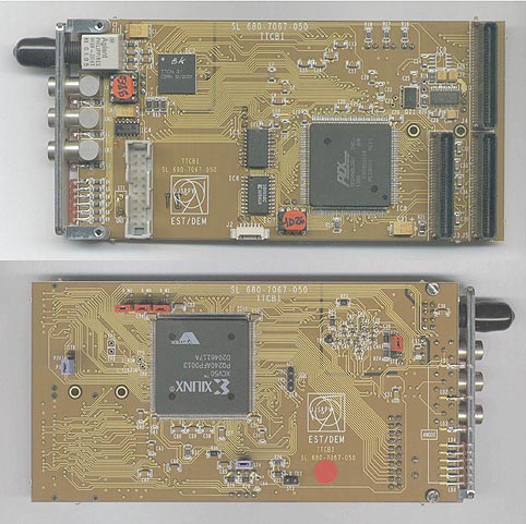
A TTC beam instrumentation receiver module (TTCbi) was developed by J.-J. Savioz for the reception of the beam-synchronous timing (BST) signals which will be broadcast by the RD12 transmitters in the PCR. The first TTCbi was a 16/32-bit PMC module with 128 MByte/s block transfer capability which can be used for the reception of the bunch and orbit clocks and BST messages by the beam instrumentation around the LHC ring and in the transfer tunnels. Three prototype TTCbi modules were tested in the SPS in 2002 and a preliminary TTCbi Engineering Specifications document is available.
A Mk II version including enhanced programmable trigger facilities is now being developed in VMEbus format. The new module, called BOBR (Beam Observation system BST Receiver), will be a dual one which can receive the separate BST signals for LHC rings 1 and 2. Draft BOBR Engineering Specifications are available.
By means of a TTCbi or BOBR module the experiment DAQ and control systems can also receive useful messages about machine events, such as start ramp or dump, and information about the status of the LHC (operating mode, beam type and energy, No. of bunches, etc). Absolute time is also broadcast.
A general-purpose TTCrx VMEmodule was developed as part of the CMS RDPM programme. The module supports a TTCrm mezzanine board and includes an A24/D32 VMEbus interface, buffers and front panel connectors. The functionality is provided by a Xilinx XC4006E which is user-programmable in situ. This module is a convenient platform for developers who wish to start TTC development work in a VME environment.
7 boards have been built and used as TTC emulators in a full event builder chain with switch and farm units. A User Manual is available. As part of this development Macintosh LabVIEW drivers were written for the TTCvi.
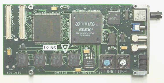
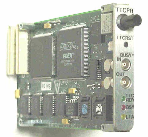
A general-purpose TTC PMC receiver (TTCpr) module has been developed as a PCI Mezzanine Card (PMC) for the ATLAS tile calorimeter DAQ by J. Dawson and the card can be made available to other groups. The functionality of the module is provided by a user-programmable Altera 10K30A which is connected to the TTCrx, an AMCC 5933 and 4 blocks of 8K x 16b FIFO.
A preliminary description of the TTC PMC receiver (TTCpr) is available. Software to interact with the module has been written by J. Schlereth. A Mk II version of the TTCpr which uses the new fpBGA TTCrx is now available.
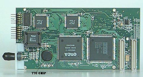
An earlier TTC simple receiver (TTCsr) board was developed by CERN EP/HC Group. The TTCsr provides some of the TTCrx signals as IEC 912 ECL front-panel outputs, and includes FIFOs to buffer TTCrx data to the PCI bus.
TTCsr Specifications and TTCsr Documentation are available.
A TTC interface module (TIM) has been developed for the ATLAS SCT by University College London. This 9U VME slave module uses a TTCrx to receive the TTC signals and transmits the required subset to all the RODs in the crate in which it resides. The TIM also generates the SCT busy signal for return to the CTP and has stand-alone capabilities for testing.
The module is described in "Timing, Trigger and Control Interface Module for ATLAS SCT Read Out Electronics", J. Butterworth, D. Hayes, J. Lane and M. Postranecky, presented at the Fifth Workshop on Electronics for LHC Experiments, Snowmass, Colorado, 20-24 September 1999.
While the gaps in the LHC bunch structure reduce the machine filling factor by about 20%, they will prove useful for adjusting the synchronisation by crosscorrelation with the event occurrence patterns.
A review of synchronization issues is given in "Timing and Synchronization in the LHC Experiments", J. Varela, presented at the Sixth Workshop on Electronics for LHC Experiments, Kraków, 11-15 September 2000.
The strategy for setting up the timing of the ATLAS experiment is described in Chapter 19 of the Level-1 Trigger TDR.
Synchronisation circuits which have been developed for the CMS calorimeter trigger are described in the paper "Trigger Synchronisation Circuits in CMS", J. Varela et al, presented at the Third Workshop on Electronics for LHC Experiments, London, 22-26 September 1997; updated 30 March 1998.
CMS Synchronisation Workshops were held on 11 November 1998 and 12 May 2000.
CMS trigger rate control is reviewed in "Trigger Throttling System for CMS DAQ", A. Racz, presented at the Sixth Workshop on Electronics for LHC Experiments, Kraków, 11-15 September 2000.
The TTC system employs Hamming checkbits which allow the automatic forward error correction by the TTCrx ASIC of all B Channel single-bit errors and the detection of all double-bit errors, as well as many others. You can find the source of the Hamming code here.
Owing to the large number of channels and the inaccessibility of the front-end electronics for repair, a number of TTC channels may be expected to be defective. DAQ Note 45 by N. Ellis discusses ideas for error detection and recovery in ATLAS readout systems.
In addition to the primary application of broadcasting signals to the front-end electronics controllers, the use of the TTC system is being studied for other possible applications, such as:
A one-day TTC Workshop was held at CERN on 30 October 1996 to review the TTC requirements of the LHC experiments, identify common elements, report current progress and plan future work. Copies of the Workshop Record have been sent to all registered attendees and may be requested by e-mail by others.
A second one-day TTC Workshop was held at CERN on 29 June 2001. Copies of the transparencies presented by the RD12 speakers are available.
A TTCmi was provided at each of the LHC-structured test beam facilities which were operated successfully in the West and North areas in May 2000 and Oct/Nov 2001. During the second run a TTCmi was provided in the GIF area as well as at H8, X5 and X7. In the first run the test beams comprised 2 µs trains of 81 bunches at 25 ns spacing, repeated once every SPS orbit of 23 µs over a slow extraction interval of 2.37 sec. In the second run they comprised 1.2 µs trains of 48 bunches at 25 ns spacing, repeated every orbit over a slow extraction interval of 1.7 sec (maximum 2.6 sec). The SPS supercycle was 16.8 sec.
During these tests the precise bunch frequency was 40.0788 MHz and SPS rephasing was implemented before each slow extraction of the structured test beam, just as it will be when the machine is used as an LHC injector. The SPS orbit signal was also provided for gating purposes. The orbit signal frequency changes by about 29 Hz during the SPS magnet ramp but metastability is avoided by a synchronizer in the PCR transmitter. During the flat top the orbit frequency is locked at 1/924 of the bunch frequency (43.375 kHz).
The RD12 timing distribution system performed satisfactorily during these LHC-structured test beam runs. The CMS X5 beam monitor team (M. Bozzo, A. Giassi, L. Latronico and A. Morelli) observed a bunch length of 2.3 ns, close to the expected length of 2.5 ns. Further details of their measurements were given in the presentation "A beam monitoring system for the CMS Tracker 25 ns test beam" by L. Latronico. There was no run in 2002 but some tests were performed in the SPS using the LHC beam provided in the P2 cycle.
The third run with LHC-structured test beams was held from 23 May to 1 June 2003. The test beams comprised 1.2 µs trains of 48 bunches at 25 ns spacing, repeated every orbit over a slow extraction interval which could be varied from 0.5 to 2.6 sec. The spill length was typically 2.2 sec and the SPS cycle length 16.8 sec. For this run, additional TTCmi were provided at X5A, X5B and H6.
An additional SPS run with LHC-structured beams will take place in September 2003. The provisional schedule is that set-up for the run will start on Wednesday September 17 in parallel with the PS MD. The run should start at 08:00h on Thursday September 18 and continue until 08:00h on Sunday September 21. Depending on the 25 ns set-up progress on Wednesday, beam could be available before Thursday morning.
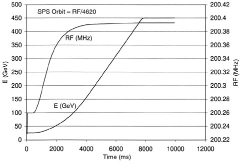
Two runs with LHC-structured test beams were held from 14 to 21 June 2004 and from 5 to 11 October 2004. The first run was perturbated by the fact that the optical cable going to H2, H4 and H6 was found cut. This run also issued some questions about the way the TTC precise frequency 40.0788MHz and the SPS frequency were rephased: The 40.078834 MHz signal transmitted by the TTC system was generated by a very stable oscillator from the RF. This frequency (Ftop) is the equivalent frequency of the RF of the LHC, on flat top, at the energy of 400GeV. This frequency was fixed and did not vary during the 25ns run. During a complete cycle (12 seconds), the SPS RF varied from 40.053MHz up to Ftop. At the “RF resync” timing, the RF was “re-phased” to Ftop, which means that the machine RF was re-phased to match the stable Ftop. This happens about 6.5s after the beginning of each cycle.
25ns Structured test beam - 21-09-06 - 29-09-06 - useful data and links:
|
ALICE Central Trigger Processor |
|
| CTP - PDR, 29 June 2004 : | http://www.ep.ph.bham.ac.uk/user/pedja/alice/ctp_preliminary_02.pdf |
|
ALICE Local Trigger Unit |
|
| LTU - PDR, 15 October 2002: | http://www.ep.ph.bham.ac.uk/user/pedja/alice/ltu_preliminary10.pdf |
| TTC Partition Timing, 20 October 2004: | http://www.ep.ph.bham.ac.uk/user/pedja/alice/ltu_timing01.pdf |
|
ATLAS Level1 - Technical Design Report extracts |
|
| TTC - Chapter 16 | http://atlas.web.cern.ch/Atlas/GROUPS/DAQTRIG/TDR/V1REV1/L1TDR_TTC.pdf |
| Strategy for setting up the timing of the experiment - Chapter 19 | http://atlas.web.cern.ch/Atlas/GROUPS/DAQTRIG/TDR/V1REV1/L1TDR_Timing.pdf |
|
ATLAS CTP |
|
| Publication | http://lhc-workshop-2004.web.cern.ch/lhc-workshop-2004/4-Parallel sessions B/52-amaral_proceedings2.pdf |
|
ATLAS LTP |
|
| Publication | http://lhc-workshop-2004.web.cern.ch/lhc-workshop-2004/5-Posters/65-farthouat_proceedings.pdf |
| User Manual | https://edms.cern.ch/cedar/plsql/doc.info?cookie=3350333&document_id=551992&version=2 |
|
The ATLAS Central Level-1 Trigger Logic and TTC System JINST Publication |
|
| 2008_JINST_3_P08002 | http://www.iop.org/EJ/abstract/1748-0221/3/08/P08002 |
|
CMS TTC web page |
|
| TTC web page | http://cmsdoc.cern.ch/cms/TRIDAS/ttc/ |
|
Readout supervisor (LHCb TTC master): |
|
| Paper | http://lhc-electronics-workshop.web.cern.ch/LHC-electronics-workshop/2002/Poster/guzik.pdf |
The RD12 TTC System was initially specified in -
A recent review of the system is given in the LECC 2002 paper "Timing Distribution at the LHC".
A short overview was given in the paper "TTC Distribution for LHC Detectors", IEEE Trans. Nuclear Science, Vol. 45, No. 3, June 1998, pp. 821-828.
Later developments were reviewed in the 1999 Status Report on the RD-12 Project, CERN/LHCC 2000-002, 3 January 2000.
Earlier work is described in the 1998 Status Report on the RD-12 Project, CERN/LHCC 98-38, 19 October 1998.
More detailed background information was given in the 1997 Status Report on the RD-12 Project, CERN/LHCC 97-29, 30 April 1997.
The TTCmi machine interface for the system is described in the RD12 working document "TTC machine interface (TTCmi) User Manual".
User notes for the VME-size TTCex and TTCtx laser transmitter modules are given in the RD12 working document TTC Laser transmitter (TTCex, TTCtx, TTCmx) User Manual.
The TTCvi VMEbus interface module is described in the RD12 working document "TTC-VMEbus Interface (TTCvi)". An earlier version (Rev 1.5) of this document is still available here.
The TTCvx VME-sized LED transmitter module for developers is described in the draft RD12 working document "TTCvx Technical Description and Users Manual".
A short overview of the TTCvi and TTCvx modules is given in the LEB 1999 paper "Modules Development for the TTC System".
Irradiation test results for the photodiode+preamp components are given in the draft LECC 2003 paper "Radiation Qualification of Commercial off-the-shelf p-i-n Receivers for the TTC system".
Technical specifications of the TTCrx timing receiver ASIC are given in the "TTCrx Reference Manual".
A list of the changes which have been implemented in the latest fabrication of the TTCrx is given in "TTCrx Modifications".
TTCrx irradiation test results are given in the LEB 2000 paper "Measurements of Radiation Effects on the Timing, Trigger and Control Receiver (TTCrx) ASIC".
A review of synchronization issues is given in the LEB 2000 paper "Timing and Synchronization in the LHC Experiments".
CMS trigger rate control is reviewed in the LEB 2000 paper "Trigger Throttling System for CMS DAQ".
Some aspects of the proposed TTC system implementation for ATLAS are described in a Trigger-DAQ Steering Group Requirement Document (Version 2.0) and the system is intended to meet the requirements specified in the ATLAS ROB User Requirements Document.
The ATLAS-SCT TTC interface module is described in the LEB99 paper "Timing, Trigger and Control Interface Module for ATLAS SCT Read Out Electronics".
The timing resolution required for the ATLAS MDT system is discussed in ATLAS Muon Note 111.
The TTC needs of CMS are summarised in a Table. Updates should be sent to A. Racz.
The timing distribution and clock management of FERMI via the service ASIC is discussed in FERMI Note 21.
Special requirements apply to the TTC system for the ALICE TOF detector.
A mailing list has been set up for TTC news and information-sharing among developers and users at CERN and collaborating institutes only. All RD12 participants are subscribed to the list and can respond to queries relevant to their areas of interest.
To join or leave the mailing list send an e-mail here with either subscribe lhc-exp-ttc or unsubscribe lhc-exp-ttc in the message body.
The RD12 TTC system will be used by all four LHC experiments and the beam instrumentation of the LHC machine and transfer lines. To ensure that maintenance is available for the lifetime of the LHC, central support will be provided by the On-line Systems section of EP/ESS Group. The supported items will include:
This section is under construction. It will eventually contain maintenance information for the TTC system components.
A portable optical power meter is useful for diagnosing problems in TTC distribution systems. The HP 8140A instruments used by RD12 are no longer manufactured but M. Joos of EP/ESS Group reports satisfactory results with the Acterna model OLP-5. Before making a measurement with a power meter, remember to select 1310 nm on the instrument and to zero it for correct calibration.
Experience suggests that the frequency of TTC system problems due to electronic component failure will in practice be negligible compared with simple problems caused by optical connector contamination. These can easily be avoided by the systematic use of impregnated lens tissue to wipe the ferrule tips every time optical connectors are mated. Such lens tissue has proven more effective than other techniques such as compressed air, alcohol swabs, proprietary sprays, etc. After cleaning connectors, inspection with an inexpensive 100x pocket fibrescope (such as Panasonic FF-394 or 3M/TrueView 6355-A) is recommended.
If this advice is not followed and contamination is spread by indiscriminately swapping modules or fibres, all the affected optical connectors should be cleaned including those inside the modules themselves. Due to the use of pigtailed components with front panel interconnector bushings in laser transmitters and optical tree couplers this is easily accomplished.
RD12 would like to acknowledge the excellent cooperation and support received from members of CERN SL and ST Divisions. In particular the contributions of R. Jones and J.-J. Savioz of SL/BI Group, G. Beetham of SL/CO Group, Ph. Baudrenghien and D. Stellfeld of SL/HRF Group and L.K. de Jonge and O. Olsen of ST/EL Group have been invaluable to the project.
Appendix: reader for .pdf files
Acrobat Reader software for viewing and printing the TTC document files in
.pdf format is available here ![]() for Macintosh, Windows, SPARC, HP, SGI and DOS platforms.
for Macintosh, Windows, SPARC, HP, SGI and DOS platforms.